

EtherChannel is a technology wherein we bundle physical interfaces together to create a single logical link. It is also known as Link Aggregation. It provides fault-tolerant and high-speed links between Cisco switches and routers and is often seen in the backbone network. The approved open standard is called 802.3ad, which works with other vendors and is often called LAG.
How Does EtherChannel Work?
We can assign up to 16 physical interfaces to an EtherChannel, but only 8 interfaces can be active at a time. You can form EtherChannel between two, four, or eight active Fast, Gigabit, or 10-Gigabit Ethernet interfaces, with an additional one to eight inactive interfaces which can become active as the other interfaces fail.
To create an EtherChannel, all of the interfaces should have:
- Same Duplex
- Same Speed
- Same VLAN Configuration (Ex. native VLAN and allowed VLAN should be same)
- Switch Port Modes should be the same (Access or Trunk Mode)
EtherChannel can look at the following options to decide which physical link to send data over:
- Source MAC Address
- Destination MAC Address
- Source and Destination MAC Address
- Source IP Address
- Destination IP Address
- Source and Destination IP Address
- Source TCP/UDP Port
- Destination TCP/UDP Port
- Source and Destination TCP/UDP Port.
These options depend on the hardware and software, and there could be more options on other models and software versions.
The 2 Etherchannel Protocols
We also have two protocols that we can use, aside from manually configuring EtherChannel.
Port Aggregation Protocol (PAgP) – is a Cisco proprietary EtherChannel protocol where we can combine a maximum of 8 physical links into a single virtual link.
Link Aggregation Control Protocol (LACP) – is an IEEE 802.3ad standard where we can combine up to 8 ports that can be active and another 8 ports that can be in standby mode.
Why Do We Need EtherChannel?
Below are the advantages and benefits of implementing EtherChannel on our networks:
Increased Bandwidth
In our network planning, we always take into account the cost. For example, our company needs more than 100 Mbps bandwidth, but our hardware only supports Fast Ethernet (100 Mbps). In this case, we can opt not to upgrade the hardware by implementing EtherChannel.
Also, we might think that if we have two or more links between two switches, like in our figure above, then we can utilize the full bandwidth of these links. But, in a traditional network setup, Spanning Tree Protocol (STP) blocks one redundant link to avoid Layer 2 loops. Our solution to this problem? EtherChannel.
EtherChannel aggregates or combines traffic across all available active links, which makes it look like one logical cable. So in our example, if we have 8 active links with 100 Mbps each, that will be a total of 800 Mbps. If any of the physical links inside the EtherChannel go down, STP will not see this and will not recalculate.
Redundancy
Since more than one physical connection is combined into one logical connection, EtherChannel enables more available links in instances where one or more links go down.
Load Balancing
With load balancing, we are able to balance the traffic load across the links and improves the efficient use of bandwidth.
NOTE
Cisco does not offer round-robin load balancing for EtherChannel as it could potentially result in out-of-order frames.
Need of EtherChannel –
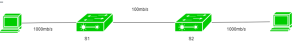
Here is a topology in which two switches are connected with one PC each. The link between the switches and PC is 1000mb/s and the link between the switches is 100mb/s.
Now, suppose if you want to send traffic of more than 100mb/s then we have congestion as the link between the switches is of 100mb/s only and packets will start dropping. Now, to solve this problem, we should have a high-speed link between the switches. To achieve this, We can simply replace the current link with a high-speed link or we can bundle up more than one link of the same speed of 100mb/s. By forming an EtherChannel, you can bundle up more than one link into a single logical link.
But, as you connect the switches with more than one link, STP (Spanning Tree Protocol) will block the least redundant link. As we have made an EtherChannel, all the links (that are grouped as one logical link k) will be treated as single logical links therefore no link will be blocked and also, it will provide us high-speed link and redundancy in our network.
Criteria – To form an EtherChannel, all ports should have:
- Same duplex
- Same speed
- Same VLAN configuration (i.e., native VLAN and allowed VLAN should be same)
- Switch port modes should be the same (access or trunk mode)
EtherChannel protocols – To form an EtherChannel, there are 2 protocols, port aggregation Protocol (PAgP) and link aggregation control protocol (LACP).
- Port Aggregation Protocol (PAgP) –
The Cisco proprietary protocol Port Aggregation Protocol (PAgP) is an EtherChannel technology. It’s a type of data/traffic load balancing that involves the logical aggregation of Cisco Ethernet switch ports. A PAgP EtherChannel can merge up to eight physical links into one virtual link. LACP, or Link Aggregation Control Protocol, is an IEEE open standard. These are namely: - ON:In this mode, the interface will be a part of EtherChannel but no negotiation takes place.
- Desirable:In this mode, the interface will continuously attempt to convert the other side interface into an EtherChannel.
- Auto:In this mode, the interface will become a part of EtherChannel if and only if it is requested by the opposite interface.
- Off:No EtherChannel configured on the interface.
Configuration –
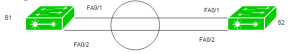
There is a small topology in which 2 switches S1 and S2 are connected with each other and we have to bundle these two links into a single logical link.
S1(config)# interface fa0/1
S1(config-if)# channel-group 1 mode desirable
S1(config)# interface fa0/2
S1(config-if)# channel-group 1 mode desirable
S1(config)# interface port-channel 1
S1(config-if)# switchport trunk encapsulation dot1q
S1(config-if)# switchport mode trunk
Here, the user has used the mode desirable and switch-port mode trunk. The modes should be the same on both switches therefore the user will configure this on the other switch also.
Now, configuring on switch S2:
S2(config)# interface fa0/1
S2(config-if)# channel-group 1 mode desirable
S2(config)# interface fa0/2
S2(config-if)# channel-group 1 mode desirable
S2(config)# interface port-channel 1
S2(config-if)# switchport trunk encapsulation dot1q
S2(config-if)# switchport mode trunk
- Link Aggregation Control Protocol (LACP) –
Link Aggregation Control Protocol is an IEEE protocol, originally defined in 802.3ad, used to form an EtherChannel. This protocol is almost similar to Cisco PAgP. There are different modes in which you can configure your interface. These are namely: - ON:In this mode, the interface will be a part of EtherChannel but no negotiation takes place
- Active:In this mode, the interface will continuously attempt to convert the other side interface into an EtherChannel.
- Passive:In this mode, the interface will become a part of EtherChannel if and only if it is requested by the opposite interface.
- Off:No EtherChannel configured on the interface.
Configuration –
Taking the same topology, you will now configure LACP on both switches. First, configuring for S1:
S1(config)# interface fa0/1
S1(config-if)# channel-group mode active
S1(config)# interface fa0/2
S1(config-if)# channel-group mode active
S1(config)# interface port-channel 1
S1(config-if)# switchport trunk encapsulation dot1q
S1(config-if)# switchport mode trunk
Now, configuring for S2:
S2(config)# interface fa0/1
S2(config-if)# channel-group mode active
S2(config)# interface fa0/2
S2(config-if)# channel-group mode active
S2(config)# interface port-channel 1
S2(config-if)# switchport trunk encapsulation dot1q
S2(config-if)# switchport mode trunk
